
Trane Zone Sensor Wiring Diagram
Trane believes that responsible refrigerant practices are important to the color coded. Contact your trane sales office about other compatible zone sensors.

Trane VariTrac Dampers Installation and Maintenance Manual
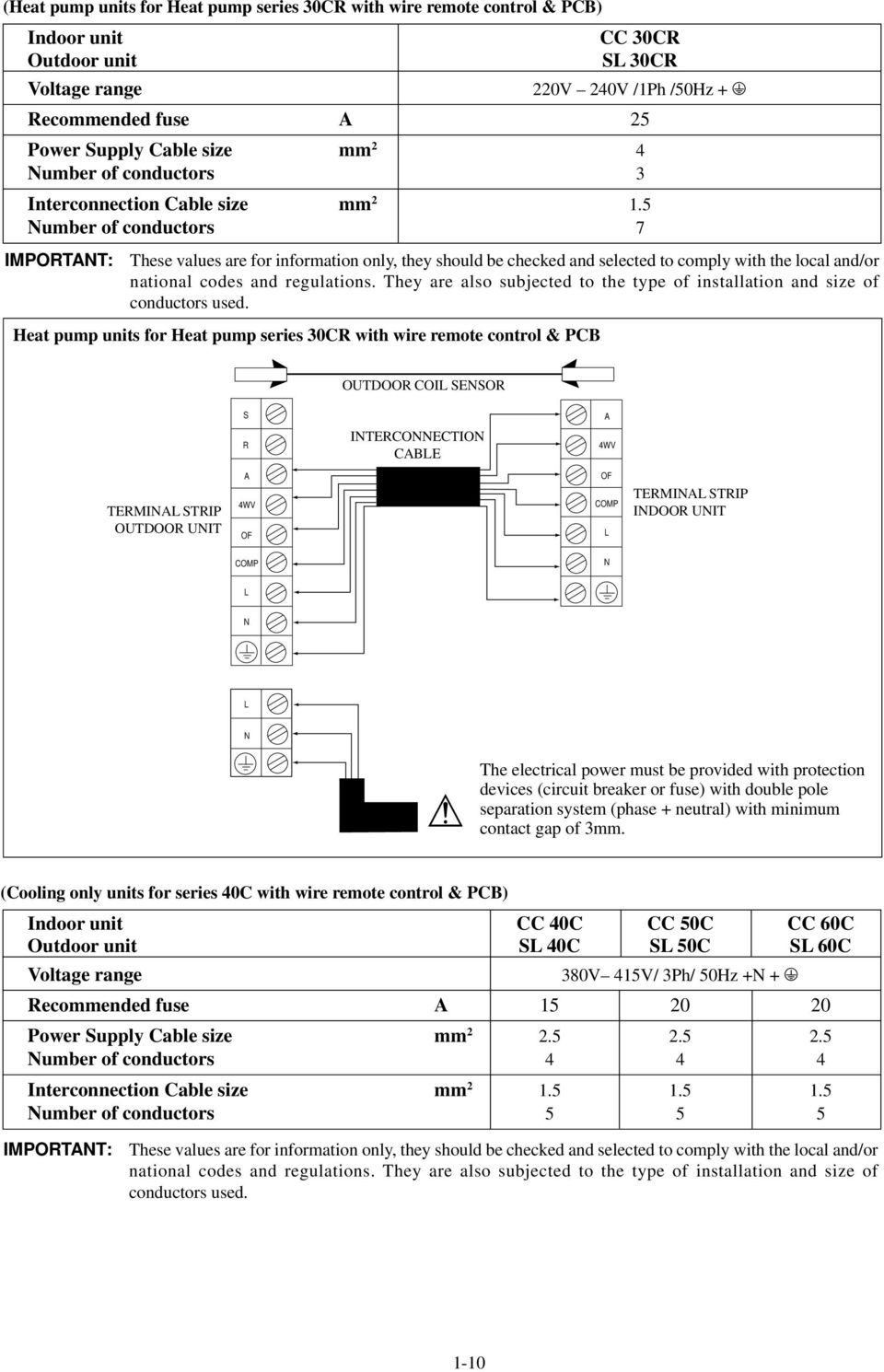
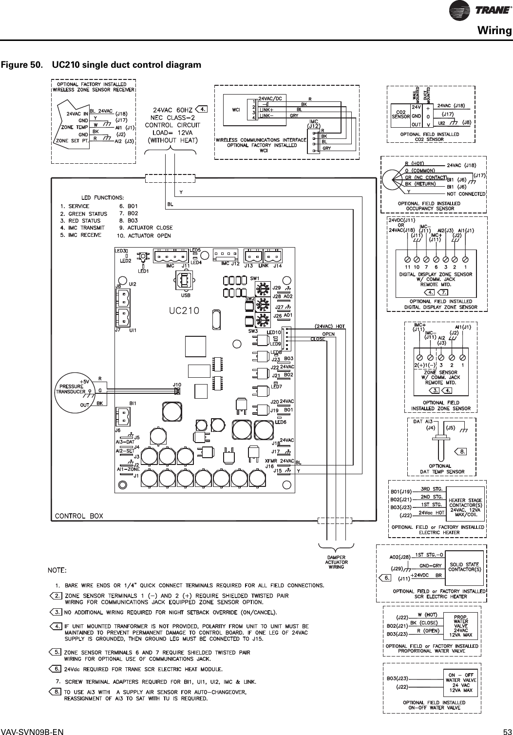
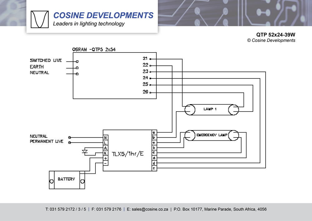
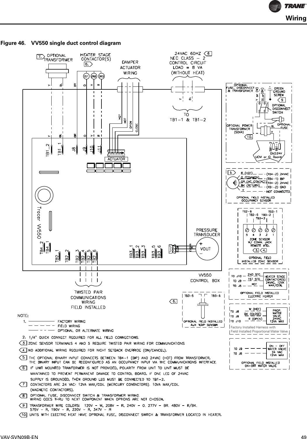
Wiring diagram contains numerous detailed illustrations that show the connection of assorted products.

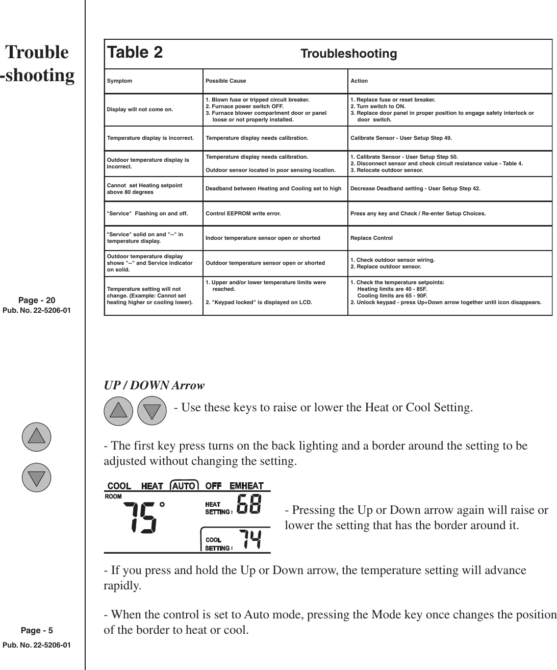
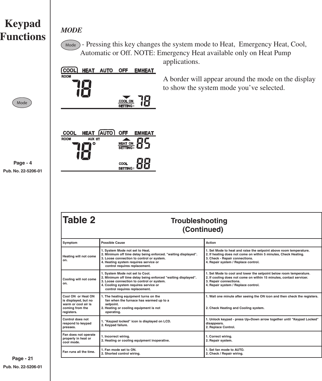
Trane zone sensor wiring diagram. • a liquid crystal display (lcd) with symbols for zone temperature, temperature setpoints, system operating modes, day of the week, time of day, and occupancy settings. Behind a pain to remove, replace or fix the wiring in an automobile, having an accurate and detailed trane zone sensor wiring diagram is. Count on trane to keep
It has the following features: It contains directions and diagrams for various types of wiring methods along with other items like lights, windows, and so on. It also allows the tenant to request temporary timed override system operation that permits the building conditions to remain in occupied comfort conditions.
Replace supply fan access panel. Ensure that the wires are connected to the appropriate terminals at the unit controller. Zone sensors are available in a variety of configurations.
Including installation, operation and programming of tijcs refer to individual zone sensor wiring diagrams for. Table 1 describes the features of the five trane zone sensors that are available for use with tracer vv550/551 vav controllers. Trane was the first to introduce the micro.
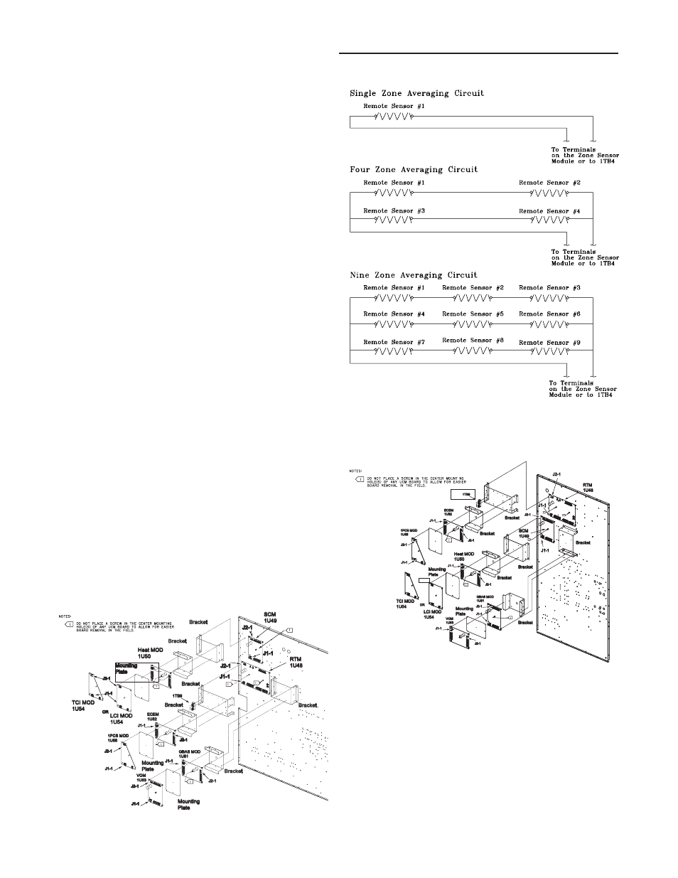
And ventilation override wiring diagram. On trane 6400 wiring diagram. Zone sensor averaging in some applications 1 remote sensor does not give a good representation of the zone temperature.
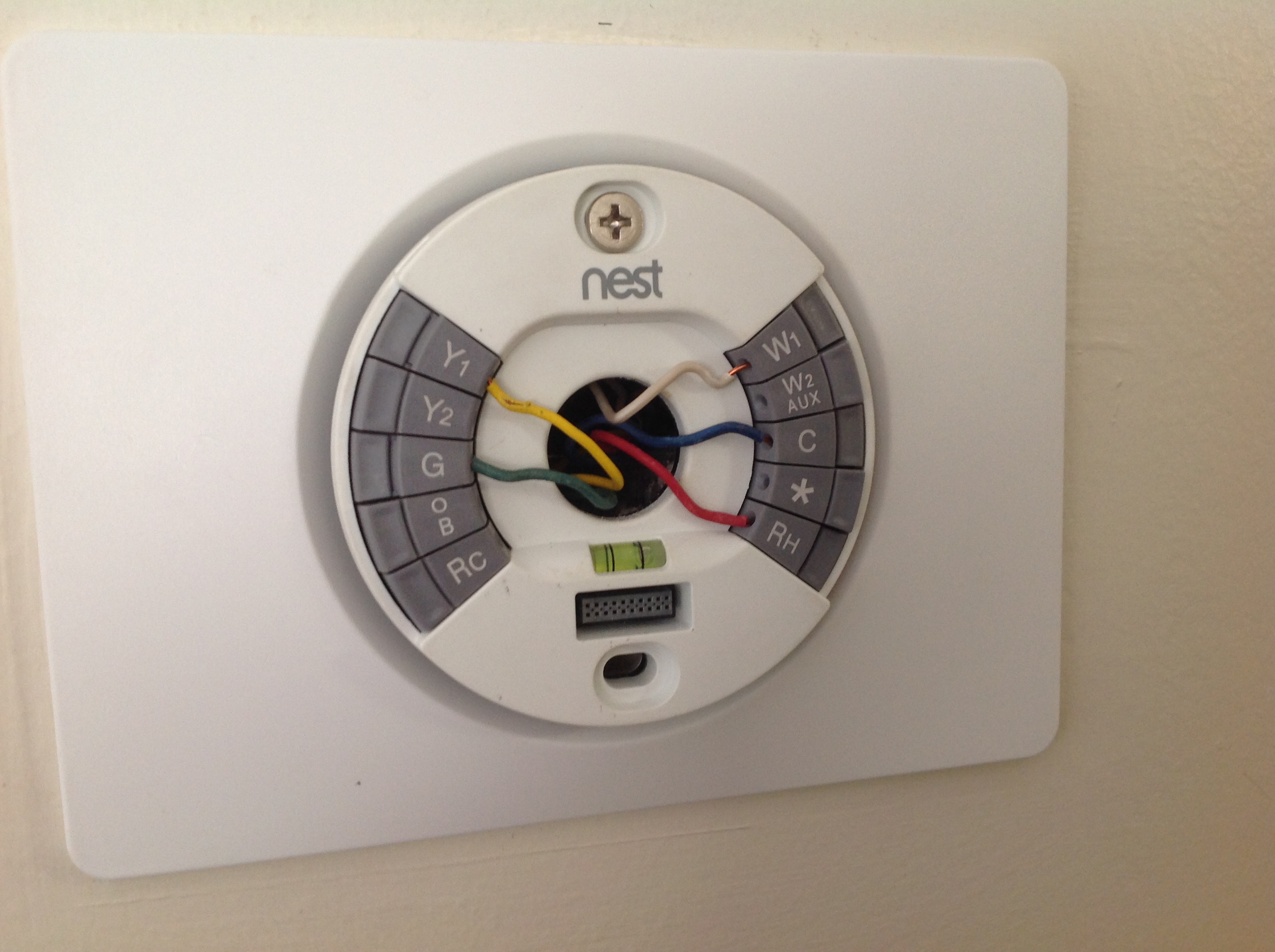
Route low voltage external field wiring along with and secure to existing low voltage zone sensor or thermostat wiring. A sen updated programmable zone sensor installation manual. To wire the sensor to the unit controller:
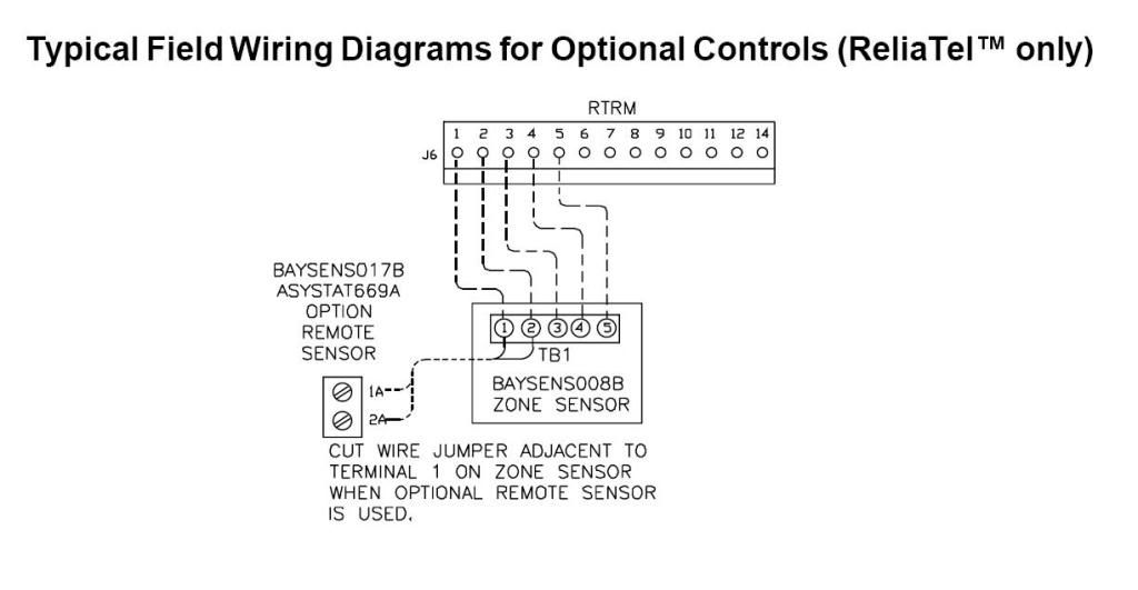
To wire the sensor, use the appropriate diagram illustrated in"wiring diagrams," p. Remote zone temperature sensor (2 wires optional) zone sensor connection diagram. Monitors its zone sensors and allows each zone to vote its needs, which are figure 5:
Trane commercial touch screen programmable zone sensor. The same five sensors are shown in figure 5. A wiring diagram is a simplified conventional photographic depiction of an electric circuit.
This electronic sensor can be used with.sep 21, · there is no wiring diagram on any of the panels nor with the unit paperwork that came with the unit. Wireless zone sensors combination zone sensor co2 zone sensor trane sensors are integral to the performance of a trane building controls system throughout the building lifecycle. Trane zone sensor analog inputs comm5 (lontalk) out in comm5 (lontalk) wiring diagram for the zn511 zone controller.
The tracer uc400 controller is compatible with the latest wireless zone sensors available from trane. Co 2 sensor connections for. Trane wireless sensors take advantage of advanced technology to overcome installation obstacles of time and cost and minimal ongoing maintenance.
The resistance of the averaging circuit must duplicate the resistance of a single sensor. On trane sensor sen02076 wiring diagram. Trane wiring diagram schematic diagram trane thermostat wiring diagram uploaded by anna r.
The trane ® programmable zone sensor (p/n x1379088401) can be used with ucp, reliatel, and intellipak control units. Table 1 describes the features of the five trane zone sensors that are available for use with tracer vv550/551 vav controllers. Zone sensors for use with tracer.
Wireless zone sensor receivers are available as a factory installed option. Will be done in the factory unless zone sensor options are selected to be wall mounted. Zone sensors for use with tracer.
Zone sensors are available in a variety of configurations. Trane sensor sen02076 wiring diagram trane®wired temperature sensors are compatible with any trane unit no no yes x na sen no single off/on/ auto/low/ med/high. The same five sensors are shown in figure 5.
Insert each wire into the appropriate location in the terminal block (see the table in figure 1). Contact your trane sales office about other compatible zone sensors. For tracer uc400, reliatel and symbio 800 controls.
Applying excessive voltage to the sensor will permanently damage it. Read this manual thoroughly before operating or servicing this unit. Replace compressor/control box access panel.
Narrow your search by selecting one or more options below.

Trane VariTrac Dampers Installation and Maintenance Manual

Trane Commercial Thermostat Manual
Control module locations for s_hf 30 ton units Trane
Honeywell TH8320 TStat with 50Ton package units

Unique Wiring Diagram for American Standard Gas Furnace
Trane Cleaneffects Wiring Diagram Gallery Wiring Diagram
31 Trane Xt500c Thermostat Wiring Diagram Wiring Diagram

Trane Voyager Ycd Wiring Diagram
Trane Ycd Wiring Diagram

Outdoor Unit Wiring Diagram Wiring Diagram

Trane Programmable Zone Sensor, X1379088401 Owner's Manual
![]()
Trane Voyager 12.5 to 25 Tons Installation and Maintenance
Trane Sensor Sen02076 Wiring Diagram
Trane Voyager Ycd Wiring Diagram
trane tcont401an21ma wiring diagram Wiring Diagram
Trane 6400 Wiring Diagram
trane tcont401an21ma wiring diagram Wiring Diagram

Trane VariTrac Dampers Installation and Maintenance Manual
Baysens011b Thermostat Wiring Diagram