
Digital Clock Circuit Diagram
A digital clock is a type of clock that displays the time digitally (i.e. 2.1 design procedures for easier design, the general circuit of the digital clock is divided into three sub sections namely;
Simple Digital Clock Circuit Diagram nerv

A digital timing diagram is a representation of a set of signals in the time domain.

Digital clock circuit diagram. [digital stopwatch circuit] circuit diagram. 12h/24h digital clock circuit design using 7493. Will generate a 1 ppm (pulse per minute) signal to the minutes block.
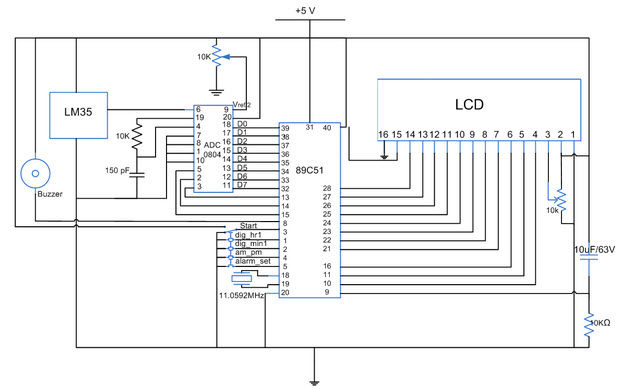
An external clock can be given to clk in pin no.4. A suitable rc circuit is connected between. It is due to the temperature sensor embedded in it.
This is a basic circuit of car horn and lamp flasher that starts playing the vehicle horn at whatever point your vehicle is backward rigging. (clocked rs flip flop logic diagram). The circuit (first diagram) utilizes double clock ne556 to create the sound.
In numerals or other symbols), as opposed to an analog clock, where the time is. Moore machine state diagram, mealy machine state diagram, karnaugh maps digital logic design engineering electronics engineering computer science It is a tool that is commonly used in digital electronics, hardware debugging, and digital communications.
Moreover it also has features like automatic recharger, under voltage lockout, current monitor and two leds for indication of charging mode and termination signal. The working of the block diagram is described in detail here. Download high resolution image of circuit diagram:
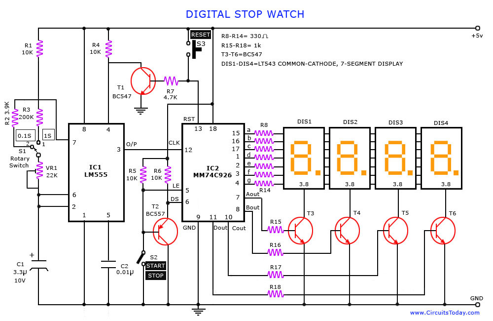
Digital stopwatch circuit diagram and explanation. Its connections are shown in stopwatch circuit diagram given below. The basic circuit diagram is shown below.
One using 8051 microcontroller and the other using atmega8 microcontroller. Tp4056 schematic circuit diagram is here. The 4 blocks of a digital clock are.
1 hz clock generator to generate 1 pps (pulse per second) signal to the seconds block. The frequency counter uses ic 555 timer to provide clock signals at a precise time. The time taken to convert the analog to digital value depends on the clock source.
Also, learn the design of synchronous counter. The circuit diagram of this can be done using two timers, counters, 8051 microcontrollers, potential resistors, square wave generator, and lcd display. Circuit diagram and working explanation:
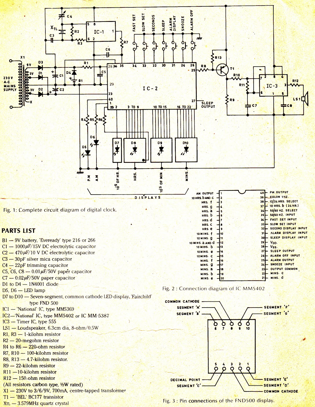
To avoid blocking up space, the alarm module is provided a separate digital clock circuit block diagram. Pulse generator for digital clock. Internal adc of this ic reads the voltage that to be measured and compare it with an internal reference voltage and converts that into the digital equivalent.
You can see the digital clock displaying the room temperature value. Additionally tp4056 is compatible with micro usb as well as adapter. Clock pin (1) and carry output pin(5) of u4 ic is directly connected to clock pin (1) of second seven segment decoder(u3).
It consists of a clock input circuit and the correct input signal. Working of this digital voltmeter circuit is very simple. In this project, i will show you how to design a digital temperature sensor circuit.
Adc needs a clock to operate. And two seven segment are connected with these decoder (u3 and u4). Adc inside the ic is integrating converter or dual type analog to digital converter.
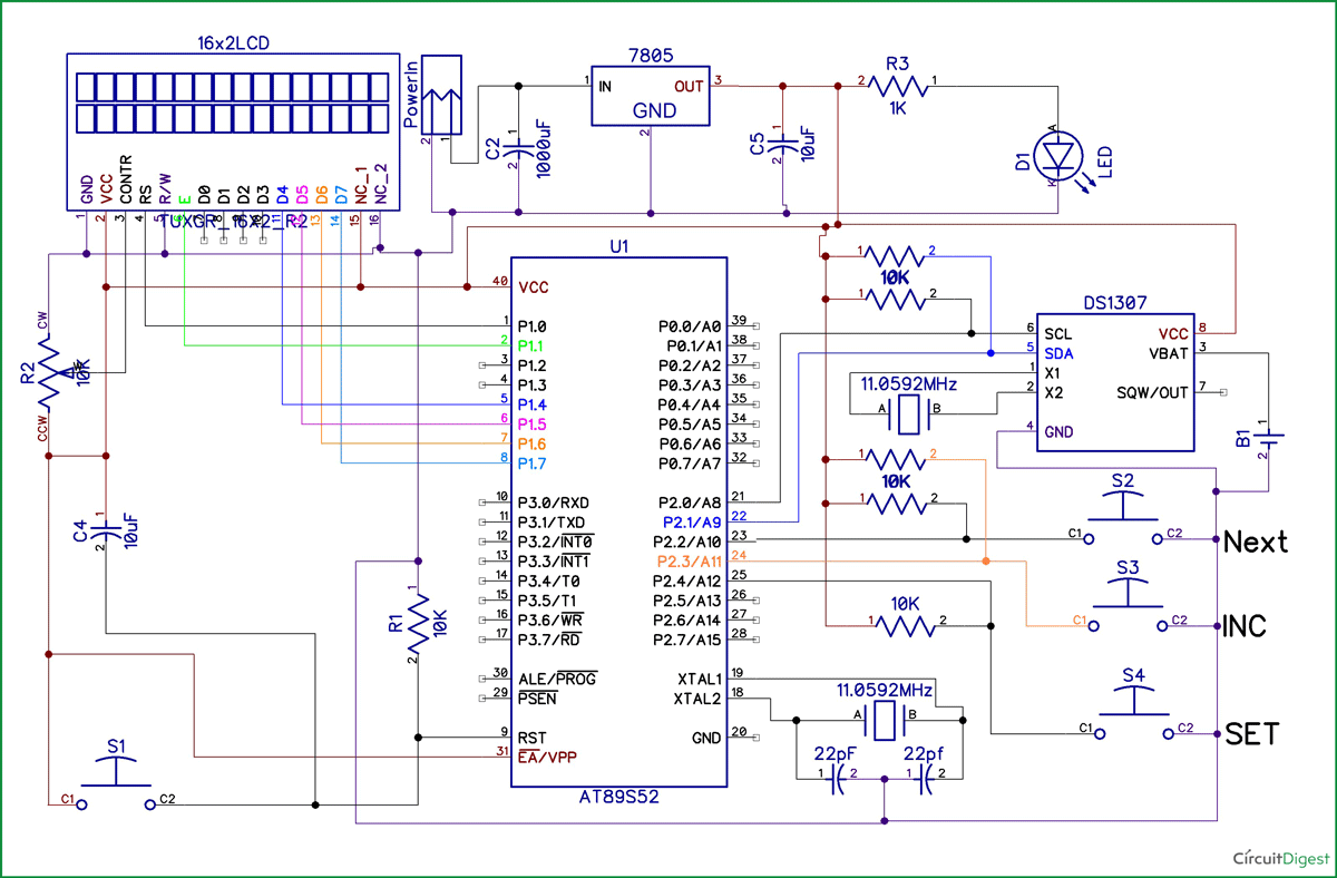
One push button is used to. The main principle of both the circuits is the 8051 controller continuously reads the data from real time clock ic's and process it in correct order to display the time on lcd. One of the clocks is wired as an astable multivibrator to produce the tone and the other is… read more »
The above circuit consists of the ics which we discussed before. In the process, i will explain two circuits: Parts of this section, might seem like the repetition of he logic of the circuit discussed before, but bear it with me.
A timing diagram can contain many rows, usually one of them being the clock. In this article, we will discuss the circuit, operation and timing diagram of synchronous up counter, synchronous down counter and synchronous up/down counter. Circuit diagram is obtained and implemented.
We will be using only basic cmos ics and pure logic to build the circuit, yet this circuit can be easily replicated by beginners in electronics.

Programmable Digital Timer Circuit Diagram

Simple Digital Clock Circuit Explained Electronic Circuit Projects

Digital Clock Circuit with Seconds and Alarm Time Display Best Engineering Projects

FYP Digital Clock circuit
Digital Clock using 8051 Microcontroller with RTC DS1307
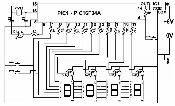
Digital Clock [PIC16F84]

Circuit Wiring Solution Digital Clock Circuit Diagram
Digital Clock under Repositorycircuits 24852 Next.gr
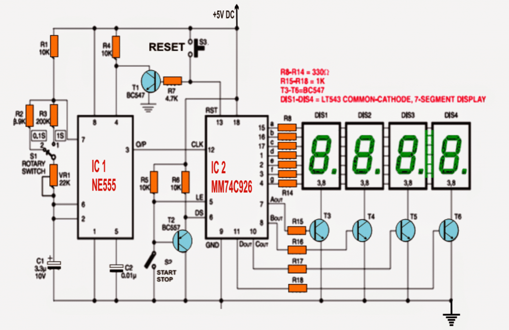
IC 555 Based Simple Digital Stopwatch Homemade Circuit Projects
Digital Clock Circuit Diagram With Pcb Layout PCB Circuits
Digital Stop Watch and Digital Timer Circuit

Digital Alarm Clock Circuit Diagram Unique Alarm Clock
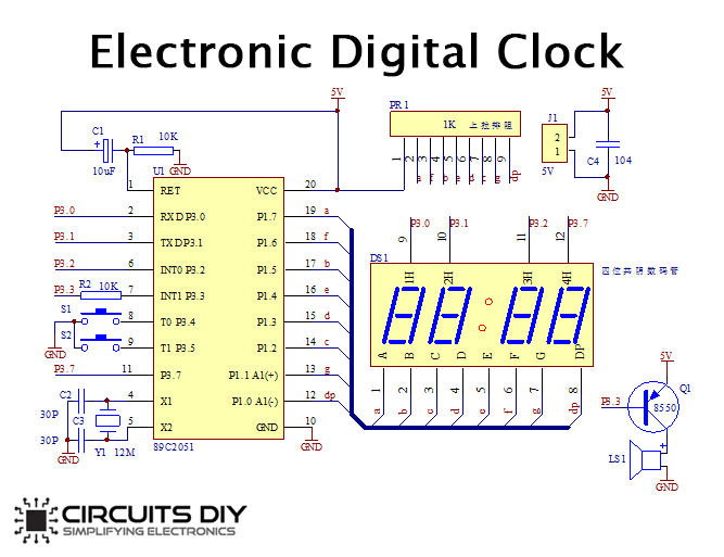
How to make Electronic Digital Clock using AT89C2051 DIY Project

Complete circuit diagram of Bangla character based digital clock. Download Scientific Diagram

LM8365 digital clock circuit board
Digital Clock Circuit Using basic ICs Electronics projects diy, Digital clocks, Electronics
How to make a simple circuit diagram of a digital clock Quora
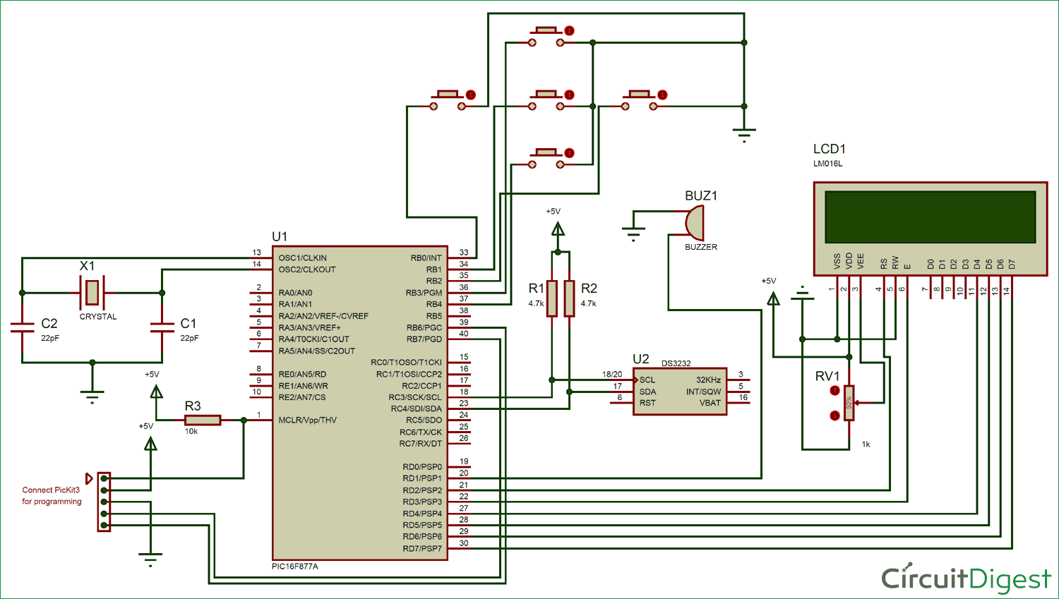
Digital Alarm Clock Circuit diagram using PIC Microcontroller
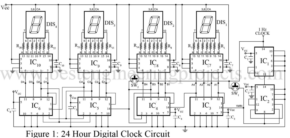
24 Hour Digital Clock and Timer Circuit Engineering Projects
