
Ic 4047 Inverter Circuit
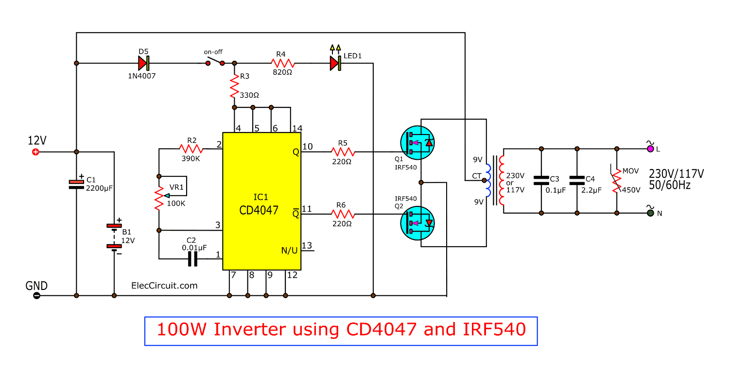
This is 100w inverter circuit. It has a wide range of input voltage (3v to 18v) and dc current input is up to ±10ma with a high operating temperature range of −55°c to +125°c.
Four CD4047 Inverter circuit 60W100W 12VDC to 220VAC
4047 circuits (11) browse through a total of 11 4047 circuits.

Ic 4047 inverter circuit. The ic is so versatile that on many occasions it easily outsmarts it's close rival, the ic 555, let's study the datasheet and pinout details of this versatile chip. It is also an astable multivibrator circuit on cmos chip. Basically, cd4047 is the 14 pin ic with having very low power consumption.
It uses 4047 ic and irf540 mosfet instead of 2n3055 transistor. Low cost 500w inverter circuit using 2n3055. My sources you are so cool!
The 4047 ic is one of the popular ic with low power consumption. The cd4047 ic is a low power cmos logic based multivibrator circuit ic. A higher channel separation stereo encoder built with 3 ic's 4066, 4047, 4013 and 741.
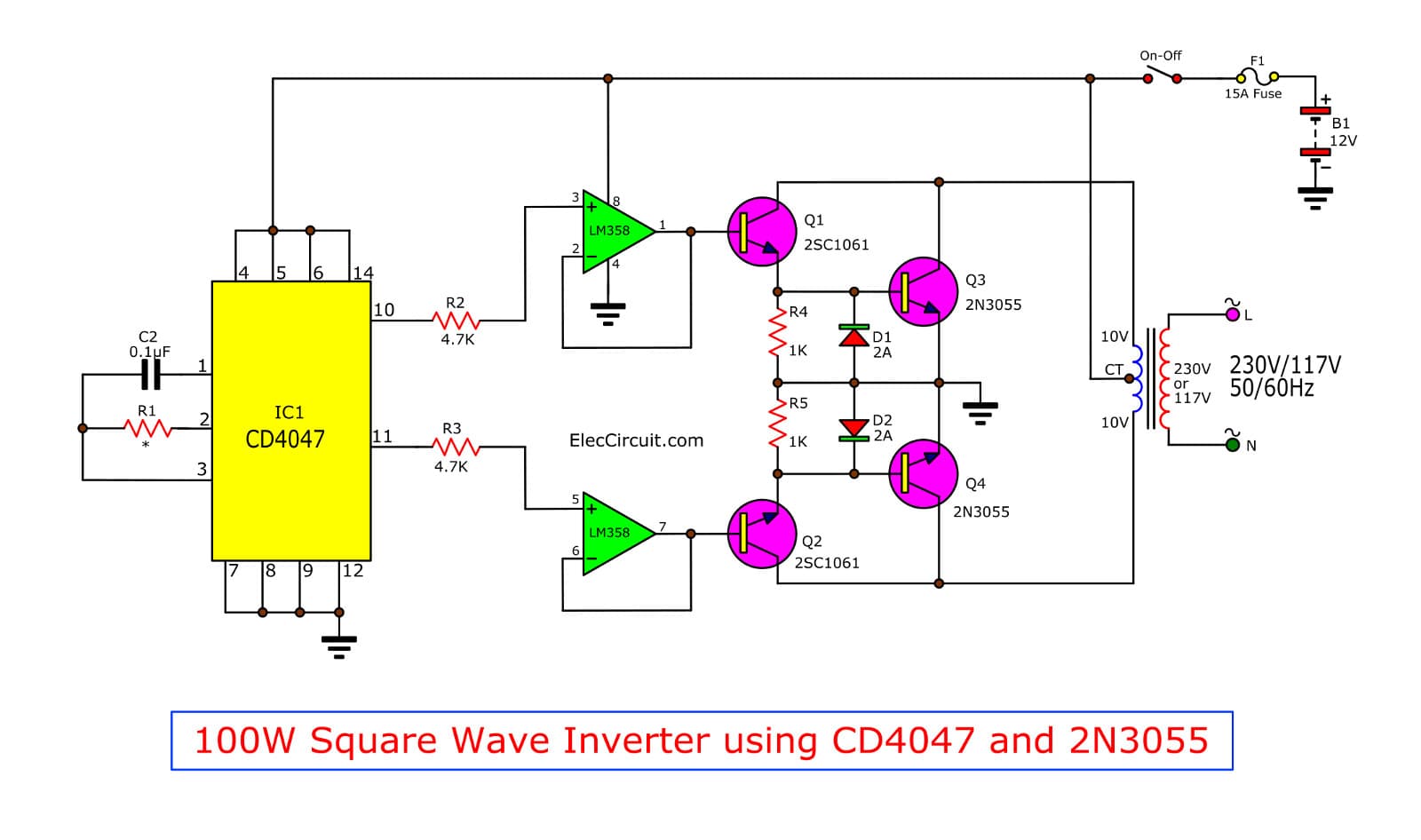
First of well for those who are not aware of inverters here is something to give you the idea about it. March 26, 2018 at 7:37 am. 100w inverter with square wave inverter through lm358, cd4047, 2n3055 & 2sc106;
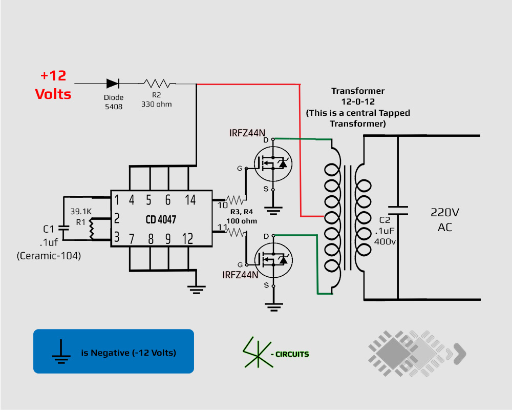
This circuit is very reliable in rendering a constant output. 60w to 100w inverter circuit; It is wired around ic 4047 and 2 mosfet irfz44n transistors and the output from the circuit is capable of deriving a load of upto 60 watts.
4047 ic is used to make different project circuits like the following. Most used in an ac inverter, square wave generator, led flasher, and more. It doesn't require bootstrapping or need special driver ics.
Here, we are using the ic to generate square and sine wave, for this. To drive the output coming from an ic, two irf540 mosfets are used. Here group of three channels.
What is not gate (inverter) simple led flasher circuit with 555 timer. We can use it in many circuits. Cd4047 is a cmos low power monostable/astable multivibrator mainly used for converting dc current signal to ac signal.
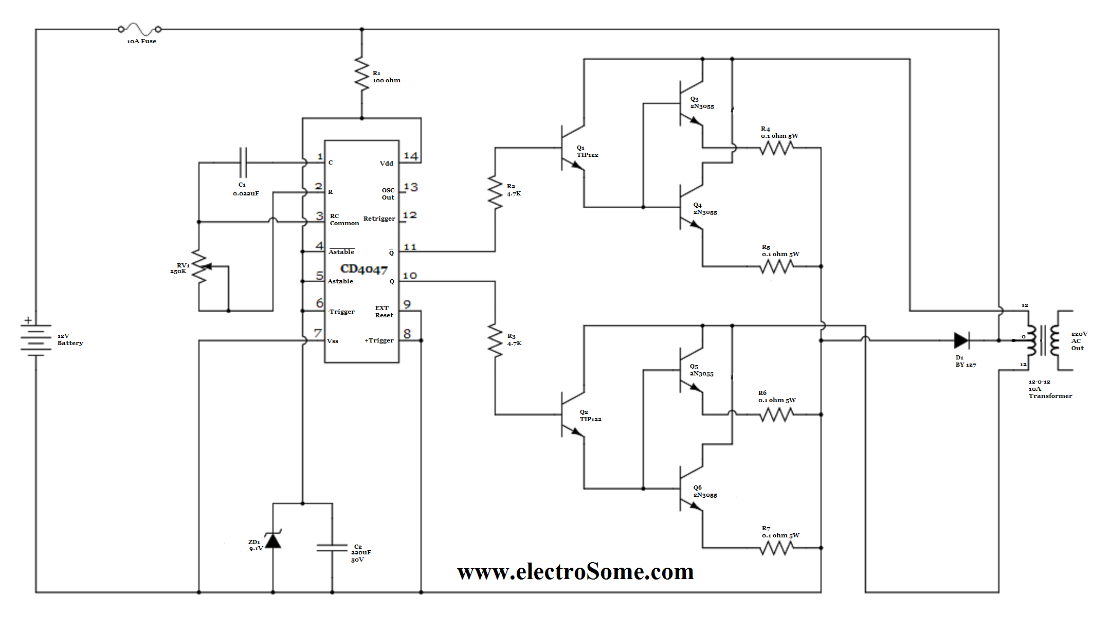
Furthermore, this ic is easy to configure for both modes and requires few external components to operate. Here is a 40 watt inverter circuit which uses ic cd4047b and some transistors to perform the desired action. The inverter circuit presented here has 4 sections.
There are six inputs including, trigger, astable, external reset and retrigger. This circuit constructed in three simple stages, the first one is multivibrator stage by using ic cd4047, it produce free running astable pulse with high peak voltages, and then second stage is power switching stage using ic uln2003 (seven darlington array) it handles 500ma current and best suitable for inductive load driving. I want to keep the efficiency of the system as high as possible.
Inverter circuits vary with the power requirements and been widely available all over the internet. The ic 4047 is one of the simplest circuits you can use for a transformerless inverter. The 4047 ic is one of the most popular inverters in the world.
Since the mosfet is a high switching. The circuit uses the cd4047 ic which works can work in astable or monostable mode. It is famous for making pulse generator and timer.
The only purpose of this ic in the circuit is to generate a duty cycle of 50%. A compact and portable 12v solar power inverter circuit that will keep away darkness. I don't believe i've read anything like this before.
But this time, i recommended, cd4047. The main reason for this has been its ability to store electric energy and consequently discharge it without the main electric power. The ic 4047 is one of those devices which promises an unlimited range of circuit application solutions.
11 thoughts on "220v 50w low power inverter circuit" my sources. With this in mind, we will dive deep into the 4047 ic. It can operate either in the monostable or astable mode.
When we say to an astable multivibrator circuit. There are 14 pins available on the ic where vss stand for ground pin and vdd is voltage supply pin. However, the resistors connected to pin 2 are rated at 0.5w and the ic has a maximum power dissipation of 500 mw.
It uses 4047 ic and irf540 mosfet instead of 2n3055 transistor. I am building this solar powered inverter:

Modifying a 4047 IC Inverter into Sine Wave Inverter
1000w Inverter Circuit With Irf540 Circuit Diagram Images

Best 60Watt Inverter Circuit Using IC 4047 12V to 220V
50W 220v Inverter Circuit Diagram Using ic 4047 50w

Four CD4047 Inverter circuit 60W100W 12VDC to 220VAC

Best 60Watt Inverter Circuit Using IC 4047 12V to 220V
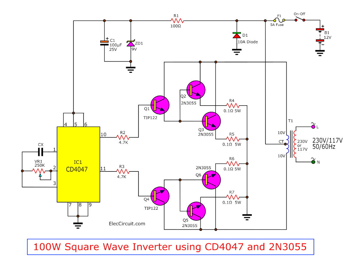
IC 4047 + 2N3055 with PCB Inverter 100W under Repository


The post explains a simple pure sine wave inverter circuit
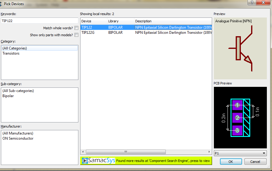
100 Watt INVERTER circuit IC 4047 pinout proteus
Four CD4047 Inverter circuit 60W100W 12VDC to 220VAC

CD4047 based Squarewave Inverter Oscillator Circuits DIY

Pure Sine Wave Inverter Circuit Using IC 4047
How to Make an Inverter by yourself? Tech Legends
Four CD4047 Inverter circuit 60W100W 12VDC to 220VAC

Inverter 100W with IC 4047 ELECTRONICS SOLUTION

IC 4047 Datasheet, Pinouts, Application Notes
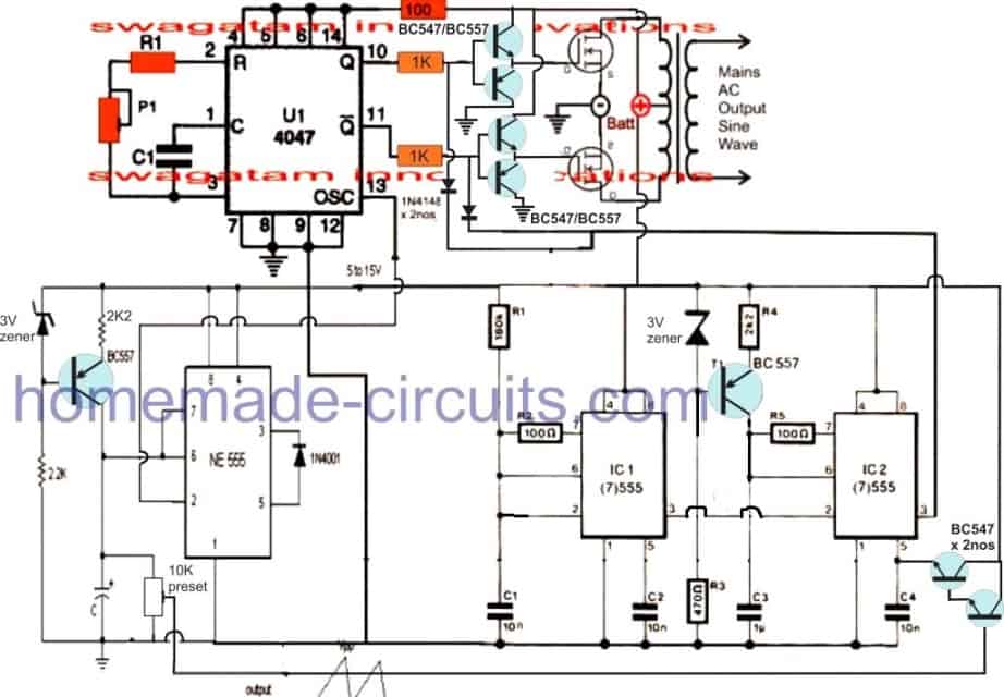
Pure Sine Wave Inverter Circuit Using IC 4047 Homemade

Inverter Circuit Diagram 5000W Pure Sine Wave Power
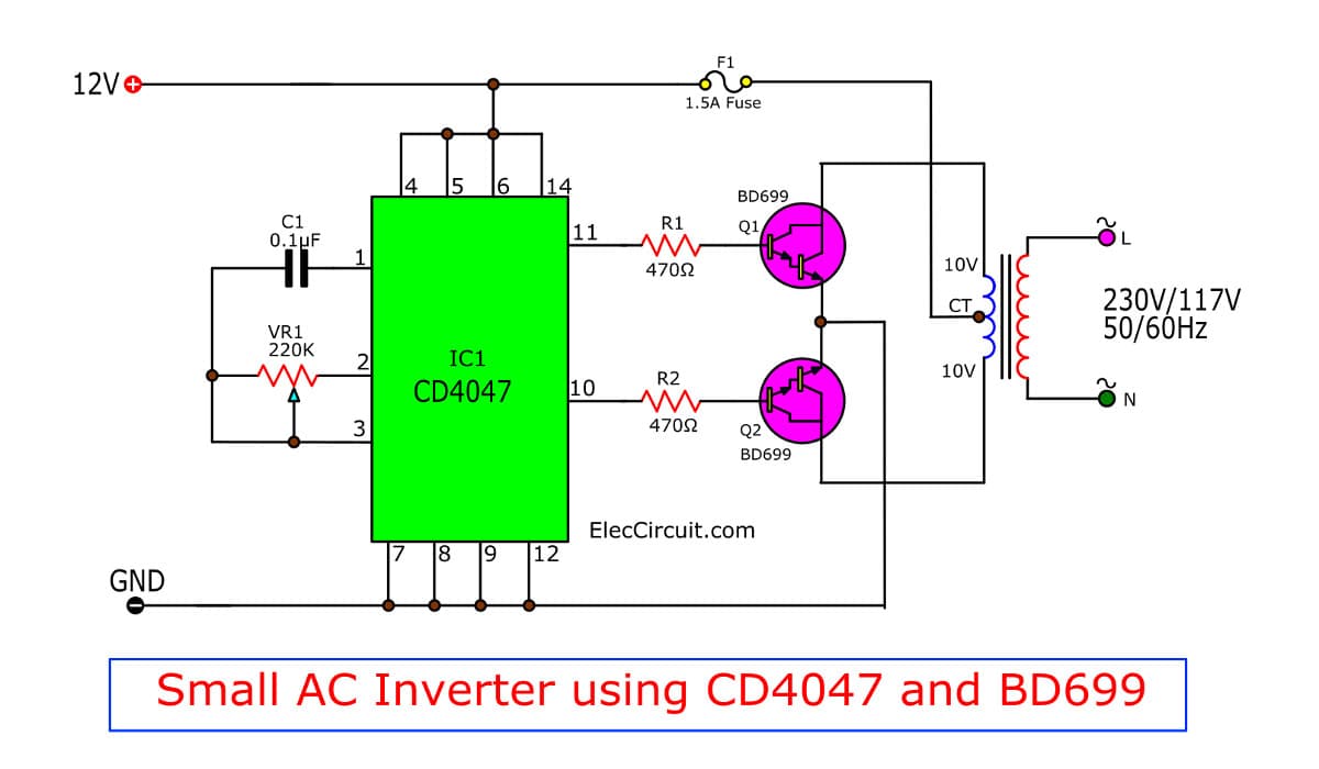
Low Power Square Wave Inverter Circuit using CD4047
